How to Have Continueous Electricy to Outlet Using a Switch
 Electrical Wire Size Required for Receptacles
How to choose the proper wire size for an electrical plug outlet or wall plug
- POST a QUESTION or COMMENT about how to install and wire electrical outlets or receptacles in buildings.
InspectAPedia tolerates no conflicts of interest. We have no relationship with advertisers, products, or services discussed at this website.
What size electrical wire should you use when hooking up an electrical receptacle (wall plug or electrical outlet)?
Here we explain the choice of No. 14 or No. 12 copper wire for 15A and 20A electrical circuits where receptacles are being wired.
This article series describes how to choose, locate, and wire an electrical receptacle in a home. Electrical receptacles (also called electrical outlets or "plugs" or "sockets") are simple devices that are easy to install, but there are details to get right if you want to be safe.
Watch out: if you are not trained in proper, code-legal, safe electrical wiring you should know that making a mistake can kill someone or set the building on fire. Better to get help from a licensed, trained electrician.
This website provides information about a variety of electrical hazards in buildings, with articles focused on the inspection, detection, and reporting of electrical hazards and on proper electrical repair methods for unsafe electrical conditions. Critique and content suggestions are invited. Credit is given to content editors and contributors.
We also provide an ARTICLE INDEX for this topic, or you can try the page top or bottom SEARCH BOX as a quick way to find information you need.
What Size Electrical Wire Should I Use When Wiring an Electrical Outlet (Receptacle)?
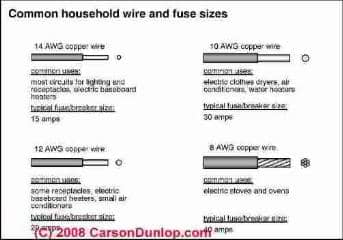
- The electrical wire used for the receptacle circuit must be the proper type in size (thickness or gauge) and number of conductors for the ampacity of the electrical circuit
- The electrical circuit must be properly protected by the right fuse or circuit breaker
- For a 15-Amp circuit use #14 copper wire (or #12 copper-clad aluminum wire). The fuse or circuit breaker feeding this circuit is rated for 15 amps.
- For a 20-Amp circuit use #12 copper wire (or #10 copper-clad aluminum wire).The fuse or circuit breaker feeding this circuit is rated for 20 amps.
- For a 30-Amp circuit use #10 copper wire and a fuse or circuit breaker rated for 30 Amps.
- For other wire sizes and a complete wire size table
see SE CABLE & BRANCH CIRCUIT WIRE SIZES vs AMPS - separate article
[Click to enlarge any image] Sketch courtesy of Carson Dunlop Associates (found at page bottom, Click to Show or Hide) a Toronto home inspection, report writing, and education company.
Note 1: it's safe and OK to use a smaller (lower ampacity) fuse or circuit breaker, such as a 15-amp fuse protecting a circuit wired with #12 copper wire.
Note 2: it's generally safe and OK to use a larger size electrical wire, and a larger wire size may in fact be required for longer wiring runs. Generally you want a 3% or less voltage drop across the wire from source to point of use. For the U.S., electrical wire sizes vs. circuit ampacity are given in National Electric Code Table 310-16.
Watch out: in complex circuits that have many connections within a single junction box you could get into trouble: the number of connections that are allowed within an individual junction box depends on the wire size and the size of the box itself. So increasing just the wire size could require that you use a larger electrical box.
Electrical Conductors: Do I Need 2-Wires? 3-Wires? 2-Wires with Ground?
 The electrical wire must have the proper number of conductors in modern electrical circuits used to wire receptacles (electrical outlets).
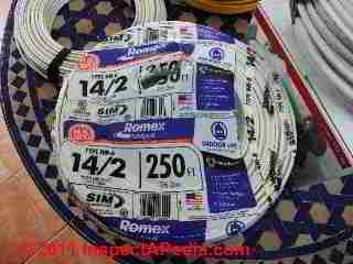
Typically an electrical receptacle is wired with two insulated wires and a bare ground wire, all three of which are encased in a plastic (NMC) or metal (BX) jacket.
You'll see this wire labeled as 14/2 Type NM B with ground (photo at left) or 14/2 Type NM C with ground.
Inside of the wire's sheathing the individual conductcors are color coded black, white, and bare (hot, netural, ground).
Details are at NUMBER of WIRE CONDUCTORS NEEDED
Also see ELECTRICAL CODE BASICS
and also SAFETY for ELECTRICAL INSPECTORS.
Question: how many electrical receptacles are allowed on a 20-amp circuit? How many receptacles on a 15-amp circuit?
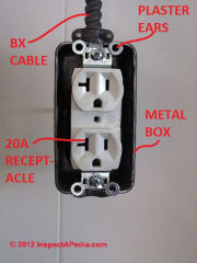 How many receptacles can be wired To one 20 amp circuit No. 12. Wire - John K.
Reply:
John K:
Our photo (left) shows a 20-Amp electrical receptacle - you can recognize it by that horizontal opening that makes the left-hand slot look like the letter "T" on its side.
In general, the Electrical Code [NEC] allows
- 10 electrical receptacles to be wired on a 15-Amp (#14 copper) wire circuit, and the Electrical Code [NEC] allows
- 13 receptacles on a 20-amp (#12 copper) wire circuit.
Watch out: When purchasing the receptacles to use on a 20A circuit, be sure to also buy receptacles that are themselves rated for 20Amp use.
You'll see that those least costly receptacles found in a big pile at building supply stores are more likely intended only for 15-Amp use.
Question: Wire size required for a 30A Wall Plug for an RV Power Drop? What about voltage drop on the circuit?
2016/09/11 Scott Davidson said:
I would like to install a 30 amp 120 volt outlet to plug in my rv camper For the length of the run it says i should use number 8 /2 wire it is about 42 feet from panel to where plug would be installed is this correct Thanks Scott
Reply: when to use a larger size electrical wire for long wiring runs - keep voltage drop under 3%
Scott
Wire sizes vs amps vs run lengths are given in the National Electric Code Table 310-16. ( Allowable ampacitys of conductors ). [Consult The Electrical Code for further details.]
Watch out: you do NOT want to provide 30 Amps to a typical electrical receptacle ("outlet" or "wall plug") as devices connected to those wall receptacles expect to be protected against overcurrent at either 15A or 20A; you'll see that a 20A receptacle looks a bit different, having an extra slot.
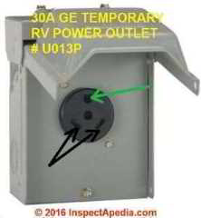
Above I illustrate a typical RV temporary outlet box for taking power to an RV. This is a GE unit sold at various electrical suppliers and building supply stores.
Another sort of 30A electrical receptacle and the wall plug that plugs into it uses a different design: you'll see that the openings in the receptacle are curved and the plug's "prongs" are also curved or in other designs the receptacle and mating plug use an angled opening and prong.
Watch out: DO NOT just run 30A to a typical wall receptacle.
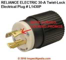
Typically a #10 wire can handle 30A 120V loads and lengths such as what you describe. Tell me where you got the requirement for #8.
You're right that it's safer and sometimes required to go to a heavier wire gauge (#8) for longer runs.
If your installation permits a 3% voltage drop, then a typical wire calculator or voltage drop calculator (there is a plethora of them online) will say you could have used a 42 foot length of #10, so #8 sounds safe to me.
Watch out: when going to a larger wire size, depending on the number of wires and connections in the electrical boxes on the circuit, you may need to go to a larger electrical box size to meet the wiring space requirements.
See ELECTRICAL BOX SIZING TABLE
Watch out also: ordinary electrical wire is not intended for use as an "extension cord" and is not intended for use being repeatedly plugged in and out nor left exposed and unsupported.
Watch out: finally, I note that you plan on running 8/2 wire? Surely you mean 8/2 with ground, right?
Check with your electrical department about required permits and safety inspections.
Voltage Drop Calculator for Long Wire Runs
I used both www.elec-toolbox.com/calculators/voltdrop.htm and Southwire; Southwire also has a nice voltage calculator and as a wire manufacturer, they of course have both an interest in proper wire use and engineers on staff.
Here's what Southwire's voltage drop calculator told us when we assumed the wire was 120V, 30A, 42 feet long, "underground / direct" though in conduit or overhead didn't change the result by much: all instances gave less than the typically-allowed maximum of 3% voltage drop.
1 conductors per phase utilizing a #10 Copper conductor will limit the voltage drop to 2.21% or less when supplying 30.0 amps for 42 feet on a 120 volt system.
Electrical Engineering Details Provided by Southwire's Voltage Drop Calculator
- 30.0 Amps Rated ampacity of selected conductor
- 1.1417 Ohms Resistance (Ohms per 1000 feet)
- 0.05 Ohms Reactance (Ohms per 1000 feet)
- 3.5999999999999996 volts maximum allowable voltage drop at 3%
- 2.644. Actual voltage drop loss at 2.21% for the circuit
- 0.9 Power Factor
**Note to User: All ampacity values are taken from the Section of 310-15 of the NEC. The conductor characteristics are taken from Table 9 of the NEC
. The calculations used to determine the recommended conductor sizes for branch circuits are based on 60°C ampacity ratings for circuits rated 100 amps or less or marked for use with #14 AWG - #1 AWG. Circuits rated over 100 amps or marked for conductors larger than #1 AWG are determined using 75°C ampacity ratings.
Calculations to determine service and feeder conductor sizes are based on overcurrent device ratings rather than actual expected loads which are conservative and may yield oversized conductors.
No calculations take into account temperature correction factors or conductor de-rating.
This voltage drop calculator is applicable only to NEC applications. It does not optimize conductor sizes for several different loads at various points in a circuit. The total combined load and length of the circuit must be used.
Consult with an engineer if your application requires more complex engineering calculations. - www.southwire.com/support/voltage-drop-calculator.htm
Reader Q&A - also see the FAQs series linked-to below
@Charles,
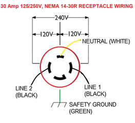
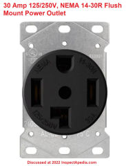
I am guessing you're describing wiring for a 30 Amp 125/250V, NEMA 14-30R Flush Mount Power Outlet, Single Straight Blade Range and Dryer Outlet Grounding, type device.
I don't know what wires you've run to the receptacle, so I am attaching a typical wiring diagram for a 4-prong receptacle.
You will see that in normal wiring the wires are
- Black 120V
- Black 120V
- White Neutral
- Green Ground
Inside the device connected to this receptacle, such as a dryer or range, use may be made of both 120V power (choosing one of the black wires and using the neutral connector) AND 240V power (choosing the two black wires).
Now sometimes an electrician may make use of an extra white wire as a current-carrying conductor. Doing so, she will indicate that the white wire in that case is NOT a neutral wire, but that it carries current: by wrapping black electrical tape around the insulation near the ends of the wire wherever it is connected.
Here is a 30 Amp 125/250V, NEMA 14-30R Flush Mount Power Outlet, Single Straight Blade Range and Dryer Outlet or receptacle, though in the photo the ground is shown at the top of the image - unlike in the wiring diagram.
Can I use the white wire for power on a 10 awg 2 wire plus ground for a 30amp 4 prong receptacle
@Gregg Linville,
First, in a shop, you certainly don't want all of your receptacles on a single circuit or you may have trouble with overloading and tripping the breaker.
So you probably want multiple circuits depending on what's being plugged in at those receptacles.
It's a common practice for electricians to run a larger wire, for example a number 10, to the more distant end of your shop to a junction box that then feeds number 12 wire to distribute receptacles in that area.
Depending on what you're connecting, you may need several of those.
Using 12 gauge wire 20 amp breaker, instal 12 outlets over 55 feet, my shop is 80 feet long what do I do to get the rest of the receptacles ran the additional 25 feet.
@nick,
a 240VAC appliance rated for 3750Watts will draw just a bit over 15A, so need a 20A 240V circuit.
Now take a look at
SE CABLE & BRANCH CIRCUIT WIRE SIZES vs AMPS
where we give tables of wire sizes and you'll see that 20A circuits use #12 copper wire,
And while a 120V circuit would be limited to about 50 ft , your 240V 20A #12 copper wire can run up to 100 ft.
we have a food warmer model E305 240 volts single phase rated at 3750 watts and I need to run power 40 feet to the unit.
what size wire, size circuit and receptacle amps should I use to plug the foodwarner unit. Thank you
@Philip Logiurato, Start at:
ELECTRICAL RECEPTACLE CONNECTION DETAILS
To wire a duplex, the second receptacle is simply connected to the "LOAD" terminals on the first receptacle.
Let us know if you have additional questions.
How to install and wire electrical outlets in a basement. Preferably a double.
Thanks for replying. I'll use the 15Amp breaker then.
Although the ceiling light and fan will be the only things normally on that circuit, my concern would be that someone years from now would unknowingly plug in a hair dryer and/or an electric heater which might make a heavy load. I guess they would figure it out when the breaker tripped.
@Sam, it would be more safe and normal wiring to protect a 14 gauge wire with a 15 amp breaker, not a 20 amp.
Take a look at the total current draw for everything on the circuit, most likely you're well below 15 amps.
Originally fed light and exhaust fan switches with 14/2 from a 20 AMP breaker in my half-bath. Nothing else on that circuit. Now I've decided I could use a receptacle on that circuit as well.
Would there be a problem if I installed a GFI receptacle along side those switches? Would the 14-2 be sufficient?
Bill
thanks for the question;
No, I would not want to run 14 gauge wire on a 20A circuit; use #12 wire, even though at the receptacle you're plugging in a portable heater that uses #16 wire in its line cord and even though the heater itself may draw less than 20A;
Figure that other people will plug in who-knows-what into that receptacle over the life of the building; if it's protected by a 20A breaker it needs to fed by #12 wire.
On a 20 amp circit is it ok to splice a 14 gauge a 16 gauge which powers a portable heater?
In good electrical wiring practice your lighting and your electrical receptacles would be on two separate circuits.
Both of them normally run on 15 amp switch is number 14 copper wire.
Of course you need electrical boxes and receptacles and switches and receptacle plates and switch plates. I can't say nothing about that links involved.
Watch out: if you're not familiar with proper and safe electrical wiring you can have the building fire or you can be shocked or killed.
Trying do you run a wire from panel box to my building to install four plugs and one switch for a light can you help me out with the materials needed
Kelan
A 15A circuit would, at normal wire lengths, use #14 gauge copper wire
What size strand wire should be use for a light fixture using 15 amp fuse
What strand wire should be ran for a wall outlet that uses 15 amp fuse
Larry
Thank you for the electrical circuit load limitations assumptions question.
The short answer is no. When electrical engineers and code writers specify the number of devices allowed on a circuit (e.g. the number of electrical receptacles or what you're calling outlets) that number is based on an assumption of less than 100% loading.
Instead it's based on the assumed total reasonable load in current or amps on the circuit.
For example a typical electrical receptacle is rated for either 15A or 20A maximum current draw. (It's permitted to install a 20A receptacle on a 15A receptacle circuit by the way).
So let's start plugging things in: if we plug in a typical small electric heater into just ONE electrical receptacle it's already sucking in electrical energy at about 11-13 Amps.
Now let's plug in a couple of floor lamps and a computer, easily drawing another 2-3 Amps.
So at just two or three receptacles actually in use we are already at the maximum that the circuit can operate safely - without overheating and risking a fire.
Now let's plug in one more electric heater, maybe a small one drawing 20A.
Remember we're analyzing a 15A electrical circuit - a string of receptacles.
Our little heater draws 9 amps.
And after just a very short time the circuit breaker will trip, shutting down that now-overloaded 15A circuit (that was trying to draw maybe 28 amps).
So unless we plugged in nothing more than a few LED-bulbed light fixtures at every circuit, we never were running electrical devices connected to all of your 10 receptacles at once.
OK so where does the limit on number of receptacles of 10 per circuit come from?
Engineers assumed a typical load of 1.5A per receptacle (that's maybe plugging in a light and another small device).
If we describe a 15A receptacle circuit, we could plug in 10 such devices for a total of 15A and thus not exceed the circuit breaker's 15A rating.
We'd be better off if that were a 20A circuit - to have a bit of margin since real live human beings don't think about the amp rating of their devices when they plug stuff in.
Bottom line: a rule of thumb is to keep the number of electrical receptacles on a circuit to 10 on a 15A circuit. On a 20A circuit you could run 13 such receptacles without tripping the breaker right-off, but
for both 15A and 20A circuits the rule of thumb is a maximum of 10 receptacles per circuit.
Also see the U.S. National Electrical Code NEC
NEC 210.23(A)(1) Branch circuits limiting any individual receptacle's load to 80% of the circuit's load rating
NEC 210.11(A) Number of circuits limited as per 220.18 maximum load
NEC 210.20(A) - maximum load on a overcurrent device is 125% of the continuous loads plus 100% of the non continuous loads
15 amp breaker circuit 14/2 wire.
Some say to limited total number of outlets to 10, meaning the total number of consistent in-use outlets, correct?
You either made a wiring error or you shorted 2 wires together or you shorted one of your wires to ground
I installed a outlet ran wire back to fuse panel 12/2 wire 20 amp breaker 20 amp outlet. It blew the breaker. What did I do wrong
Daniel:
In general it's "safe" to use a larger wire-size than required and the smallest fuse or breaker ampacity that the equipment will permit.
A 2 horsepower electric motor running on 208V draws around 13.2A to 13.8 Amps if the motor is single-phase.
A 3-phase electric motor on a 208V circuit will draw about 5 Amps, so you are well within normal limits.
Watch out: however to be sure that your electrical boxes on the circuit are large enough to hold the #10 4-conductor wire splices and to stay within code. The box fill codes set limits. If you are in the U.S., see the US NEC Table 314.16(A).
For example: if you're using a 4-inch square electrical box you can (in general) use a maximum seven (7) electrical conductors in that box.
I want to run a 220 outlet to a 2HP 3PH motor, through a AC Motor Speed Controller, for 30 feet. Am I safe in using a 15Amp breaker and #10 copper 4 conductor wire.
I can't say, William. What's the 12/2 existing length and usage?
I want to run power 600 feet to my pond. I plan to use 10/2 fort the 600 ft run and splice into a pump house light circuit with two lights at this time . Will power a light and fan at pond. Amp draw will be no more than 3 amps. Can I splice 10/2 into existing 12/2 safely?
CJ
Why not run a sufficiently-large cable into a junction box that then feeds through a spliced-on #12 copper wire to the receptacle.
What do i use when running 100 feet from my garage breaker panel to my gazebo.,for three 120v receptacles.?...#6 cable is too big to use on 20amp receptacle ,so ho was do i do this?
Hh
Thank you for the interesting wiring question.
No one with any experience would pretend that they could tell you for sure what an arbitrary wire is when found in old House wiring as people do all kinds of things over the life of the building.
Therefore it occurred to me that it could be an added ground wire. A little bit of testing with a voltmeter or digital multimeter should tell us whether the wire is hot, neutral, or ground.
I have a home that was built in the early 1900's. I am remodeling the bathroom and ran into an electrical wire that I am not familiar with. I have two wall sconces and I want just one vanity light over the bathroom mirror. The electrical wire for the old sconces is coming from the ceiling so I have plenty of wire to do what I want without running new wire.
But there is a small round white wire also coming into the old box that I have never run across before and it is coming from below, so there is not enough wire to reach the new light fixture. The wire is printed with "Code Grade 14 600V R" on it. What is this wire?
Bed
I don't know what 212 wire nor 3-bundle, is nor what Baer Black Coated wire is - sorry, perhaps you can clarify those terms or attach a photo (one per comment)
but in general, when a receptacle or light fixture is "dead" the electrician will check
- for a blown fuse or tripped circuit breaker
- for a bad electrical switch
- for a bad electrical connection right at the fixture or electrical junction box
and if those are not needing repair she will check upstream in the circuit bringing power to the failed device, looking for a loose or bad connector
Watch out: if you are not trained in proper and safe electrical work you could start a building fire or be shocked or killed - so hiring an electrician may be warranted.
I have 212 wire in my bed room bear copper coated black and coated white I have no power how can I fix this
Anon
A typical home heating pad draws 20, 40, or 60 Watts -
On a 120VAC circuit 60 Watts draws about 1/2 Amp or 0.5 Amps
A typical home 15Amp circuit uses #14 copper wiring.
So it's fine to make normal use of a home heating pad on a residential 15Amp circuit.
The issue with plugging the heating into a floor receptacle is moot if the floor receptacle is properly installed, wired, and protected against over current (that is fused for 15A on your #14 wire circuit)
Provided there is some common sense applied like:
- be sure there's no trip hazard
- be sure nobody is going to walk on, step on, or place something over the floor receptacle (damaging the line cord, plug, or receptacle) or covering the receptacle cover (say with a blanket) would of course risk a fire.
- don't force a 3-prong wall plug into a 2-prong receptacle
- Don't use an older heating pad that lacks a temperature control and that on HIGH can start a fire
- Don't use a heating pad that is worn or damaged or whose wire or plug is worn or damaged
- Don't use a heating pad that has no automatic shutoff or whose shutoff isn't working
- Don't overload the circuit into which the heating pad is connected
Can a heating pad be plugged into a floor receptacle wired with # 14 wiring.
Thanks for a great question, Rog and one that comes up from time to time.
In general it is always "safe" to use a larger diameter or gauge wire than the circuit ampacity would require.
However you can run into more subtle trouble.
The larger wire is harder to install and can be difficult or in some cases even impossible to connect to some devices such as receptacles or switches whose terminals are designed for #14 or #12 copper wire.
In addition, the required (by electrical codes) space in the electrical boxes to permit safe wiring is increased when the wire sizes are larger.
Take a look at
ELECTRICAL JUNCTION BOX TYPES
and you will find a Table of Electrical Box Sizes vs Number of Wires Allowed based on the U.S. NEC Table 314.16 (A) Metal Electrical Boxes for Devices
and in that table pay attention to
NEC 314.16(B) Electrical Box Volume Required Per Conductor (wire)
There you'll see that while you need
2.25 cu.in. per #12 wire that will be in the box
you will need
2.5 cu.in. per #10 wire that will be in the box.
Check the sizes of your electrical boxes.
That same article includes tips on solutions if you need more wiring space or more cubic inches.
Can I use #10 to feed a 20 amp circuit with 5 outlets and lighting
Cleta
Normally a 15 amp electrical receptacle circuit is wired with number 14 copper wire.
Watch out, even if you're permitted to do electrical work yourself where you live, most likely that work needs to be done with a permit and with inspections by your local electrical inspector. Don't treat that as an inconvenience. It's an important safety factor.
Watch out also, if you're not familiar with proper and safe electrical wiring you could burn down the building, be shocked, or be killed.
I am trying to redo electrical to plugins I am not sure what gauge wire
...
Continue reading at SE CABLE & BRANCH CIRCUIT WIRE SIZES vs AMPS - complete table of wire sizes, gauges, uses for buildings, or select a topic from the closely-related articles below, or see the complete ARTICLE INDEX.
Or see WIRE SIZE FAQs - questions & answers posted originally at this page.
Or see these
Recommended Articles
- NUMBER of WIRE CONDUCTORS needed
- COPPER-CLAD ALUMINUM WIRE
- SE CABLE & BRANCH CIRCUIT WIRE SIZES vs AMPS - wire sizes for branch circuits, short & long runs, & for service entry cables
- SPLICING ELECTRICAL WIRES
- UNDERGROUND SERVICE LATERALS - wire sizing guidelines
Suggested citation for this web page
SIZE of WIRE REQUIRED for ELECTRICAL RECEPTACLES at InspectApedia.com - online encyclopedia of building & environmental inspection, testing, diagnosis, repair, & problem prevention advice.
Or see this
INDEX to RELATED ARTICLES: ARTICLE INDEX to ELECTRICAL INSPECTION & TESTING
Or use the SEARCH BOX found below to Ask a Question or Search InspectApedia
...
Ask a Question or Search InspectApedia
Questions & answers or comments about how to install and wire electrical outlets or receptacles in buildings.
Try the search box just below, or if you prefer, post a question or comment in the Comments box below and we will respond promptly.
Search the InspectApedia website
Note: appearance of your Comment below may be delayed: if your comment contains an image, web link, or text that looks to the software as if it might be a web link, your posting will appear after it has been approved by a moderator. Apologies for the delay. Our Comment Box is provided by Countable Web Productions countable.ca
Technical Reviewers & References
Click to Show or Hide Citations & References
Source: https://inspectapedia.com/electric/Electrical_Outlet_Wire_Size.php
0 Response to "How to Have Continueous Electricy to Outlet Using a Switch"
Post a Comment